|
Rollforming Mill Alignment Photos
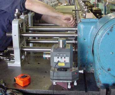
The above image shows the laser projector installed on the rollformer base. The vertical projected plane has been "bucked in" to three reference points and the target is shown setup on the bottom shaft of the 3rd forming pass.
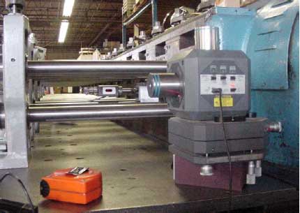
The image above provides a clear view of the Hamar three plane laser instrument. The horizontal and vertical plane rotating projectors are visible as well as the micrometer adjusted machine base. The technician is shown mounting the laser target in preparation of collecting a reading of roll shoulder offset.
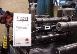
This image shows the laser target and the digital readout. The measurement shows that the shaft shoulder being inspected is 0.004" toward the drive side of the machine. When the new master shaft spacer is installed the measurement is repeated to confirm that the spacer has been ground properly. The digital readout does not require interpolation to understand and provides a clear picture of the position in space for the measured tool surface. This feature makes our alignment process faster and more accurate! We suggest quarterly inspections for rollforming mills running three shifts per day or doing short run production demanding multiple roll changes per day. Contact Welded Tube Pros for a proposal on Mill Alignment inspection, operator training and related operations. |